Foreword: Traditional remote monitoring of external pointing beacons generally uses fixed telephone dialing or directional wireless data transmission to transmit instructions and data. With the development and construction around the airport, there are many methods of fixed telephone dialing and directional wireless data transmission. Disadvantages can easily lead to monitoring failure. This article proposes a remote monitoring system for external pointing beacons based on DTU. This system is low-cost, highly reliable and stable, and has been implemented in Chongqing Airport.
I. Introduction
introduction
Marker Beacon is a special type of VHF radio beacon used in aviation. The pointing beacon radiates a fan-shaped vertical radiation field pattern upward from the ground. It is usually used in conjunction with the instrument landing system (ILS). When the aircraft flies to the area covered by the pointing beacon, it will obtain the position point information, providing the pilot with information on the location of the pointing beacon. The location point determined in establishing the flight route to the destination is a distance providing point and a checkpoint. There are three main types of pointing beacons: outer pointing beacon (OM), middle pointing beacon (MM) and inner pointing beacon (IM). The external pointing beacon is used to determine the final aircraft approach fixing point. This point is located on the same channel as the localizer and runway centerline, 4 to 7 nautical miles before the runway threshold. Typically the aircraft enters the glideslope at an altitude of approximately 1 NM (2 km) and transmits a 400 Hz tone signal on a low power (3 W), 75 MHz carrier frequency. The external pointing beacon antenna is a highly directional antenna. The effective signal area is an ellipse of 730 mx1280 m. When the aircraft receives the external pointing beacon signal while descending along the glideslope, the small purple light on the airborne receiver panel flashes. This position is generally used as the glideslope interception point. The center point beacon is usually installed 1050m before the runway threshold. This is to warn the pilot that the instrument landing system (ILS) Category I decision altitude has been passed and decide whether to go around.Internal pointing beacons are generally installed at a distance
At a position 75m to 450m from the runway threshold, the indicator light is a small white light [1].
2. Current status of remote monitoring of external indicators
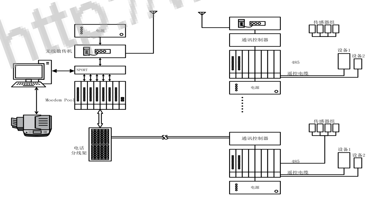
The external pointing beacon remote monitoring system consists of a central station and an end station. The central station is located in the airport navigation monitoring room, as shown in Figure 1. The end platform is located at the signpost outside each airport. Currently, two transmission methods are mainly used to monitor remote navigation station equipment.

Figure 1 Block diagram of the central station of the external pointing beacon remote monitoring system
Method 1: Use telecommunications fixed-line lines with a transmission rate of 56Kb. Due to the remoteness of the station, the landline lines are easily affected by digging and digging in the surrounding areas, and are becoming increasingly old and difficult to maintain. At the same time, there are many landline line connectors, some of which are exposed on the ground surface, and are susceptible to interference from external environments such as lightning, causing communication interruptions.
Method 2: Directional wireless transmission, the center station is equipped with an omnidirectional antenna, and the end platform is set with a directional antenna. The maximum transmission rate is only 19.2Kb. Due to the development and construction of the surrounding areas (Mu’er, Cuntan) and the construction of T3 terminal, high buildings will block and attenuate wireless signals, causing connection interruption or instability. At the same time, antennas erected outdoors need to be protected against lightning to avoid
Lightning strike.Both of the above transmission methods are no longer able to adapt to the development of existing communication transmission technology.
demand, finding optimized alternatives has become a top priority [2].
3. Construction of external pointing beacon remote monitoring system based on DTU
At present, mobile operators’ communication cellular networks have wide coverage and mature technology, and can transmit data quickly and stably. At the same time, the cost of converting fixed telephone lines to optical fiber is high, and there are many constructions around the station, and wired transmission lines are easily damaged, causing unsafe risks and affecting equipment safety. Therefore, the system design decided to use the operator’s mobile communication method for data transmission to achieve remote monitoring.
3.1 DTU function analysis
DTU (data transmission unit) is a wireless terminal. This terminal is mainly used to convert serial data into IP data or IP data into serial data. It transmits data through a wireless communication network. The DTU module mainly has the following functional features: First, it supports user serial port parameter setting. In practical applications, the types of various user equipment are different, and their corresponding serial port parameters are also different. When the DTU is connected to the serial port of the user’s equipment, the configuration parameters of the DTU can be set according to the actual parameters of the serial port of the equipment of different users.
Second, the device parameters can be customized and configured to be permanently saved. GPRS DTU is a type of communication equipment. In different applications, the parameters such as serial port baud rate, port number and IP address of the data center can be configured according to the actual situation according to the different application differences. After the configuration is completed, the set parameters are saved in storage devices such as EEPROM or EPFLASH. Third, the module can perform bidirectional conversion of serial port data. In the GPRS DTU module, an interface is specially provided for serial data communication. There are RS485 communication method, RS232 communication method, RS422 and other communication methods for data transmission. In most cases, the GPRS DTU module is designed to “transparently convert” serial port data.Without changing the original data communication content, the original data on the serial port can be converted into TCP/IP data packets in the GPRS DTU module for transmission.
deliver. Fourth, the TCP/IP protocol stack is integrated inside the module. The PPP dial-up protocol and TCP/IP protocol stack are encapsulated inside the GPRS DTU. From the hardware analysis, this module integrates the functions of wireless GPRS MODEM and the functions of embedded personal computer [3].
3.2 Implementation of software and hardware of remote monitoring system
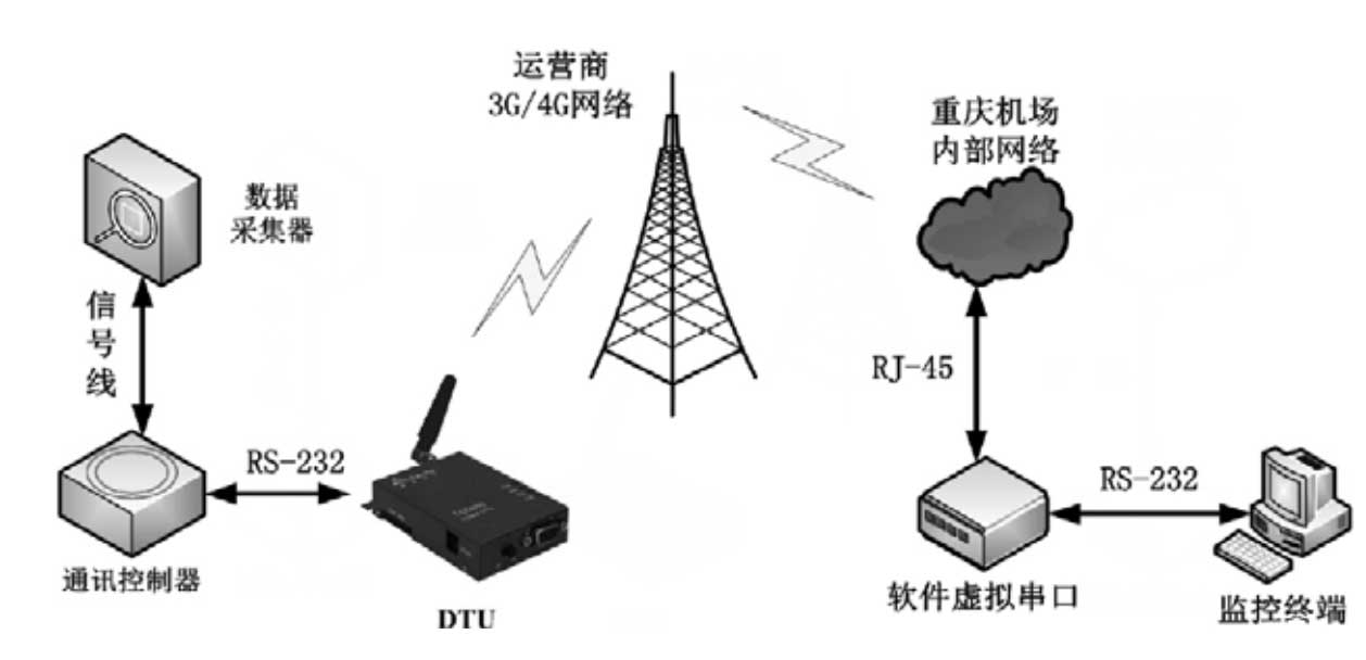
Based on the above analysis ideas, the design adopts the following architecture scheme: replace the original radio transmitter part with DTU equipment, transmit the monitoring data to the Chongqing Airport internal network through the operator’s 3G/4G network, and then convert the TCP/IP protocol into Serial port protocol receives serial port data on the terminal device to realize remote monitoring function. The schematic diagram is shown in Figure 2. Industrial grade wireless terminal equipment is selected as the hardware, Xiamen Caimao DTU: CM510-21X. The software implements Ethernet and serial port data conversion. The software forwards the data received from the DTU with the specified ID number to the virtual physical serial port specified by the computer. Set the forwarding channel on the software, set the serial port number, baud rate, data bits, etc. Related parameters. As shown in Figure 3, the setting in the figure is to forward the data of the DTU with ID number 10000001 to COM1, and at the same time, the data in COM1 will also be forwarded to the DTU with ID number 10000001.

Figure 2 Structure diagram of pointing beacon remote monitoring system
Then add the corresponding virtual serial port on the navigation monitoring computer to convert the received Ethernet data and complete the conversion to the virtual serial port data. After the DTU connection is successful, the list will reflect the corresponding DTU information, including phone number, source IP address, device connection status, etc. In addition, the status of forwarded data (incoming and outgoing data traffic) is effectively monitored. Finally, real-time monitoring of the operating data of the pointing device is realized.
