
I. Introduction
1.1 Scope
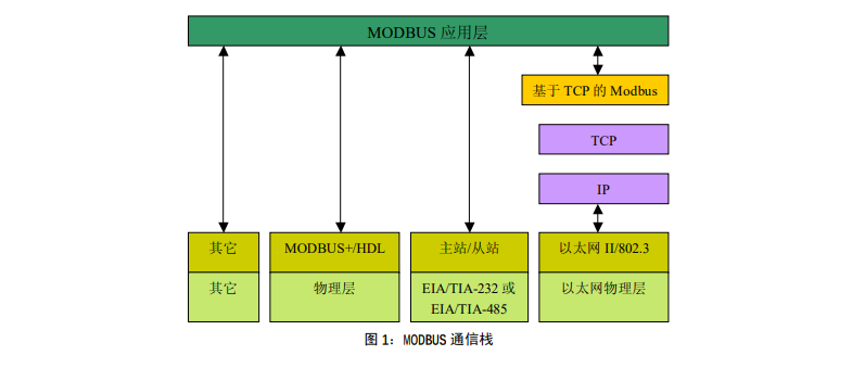
MODBUS is an application layer messaging protocol on layer 7 of the OSI model that provides client/server communication between devices connected to different types of buses or networks.
Since its emergence in 1979 as the de facto standard for industrial serial links, MODBUS has enabled thousands of automation devices to communicate. Currently, support for the simple and elegant MODBUS structure continues to be added. Internet organizations enable access to MODBUS via the reserved system port 502 on the TCP/IP stack.
MODBUS is a request/response protocol and provides services specified by function codes. MODBUS function codes are elements of the MODBUS request/response PDU. The purpose of this document is to describe the function codes used within the MODBUS transaction processing framework. 1.2 Normative reference documents 1. RFC791, Internet Protocol, Sep81 DARPA 2. MODBUS Protocol Reference Guide Rev J, MODICON, June 1996, doc#PI_MBUS_300 MODBUS is an application layer messaging protocol used for client/server communications between devices connected through different types of buses or networks. Currently, MODBUS is implemented using: TCP/IP over Ethernet. Asynchronous serial transmission over various media (wired: EIA/TIA-232-E, EIA-422, EIA/TIA-485-A; fiber optic, wireless, etc.). MODBUS PLUS, a high-speed token passing network.
1.2 Normative reference documents
1. RFC791, Internet Protocol, Sep81 DARPA
2. MODBUS Protocol Reference Guide Rev J, MODICON, June 1996, doc#PI_MBUS_300 MODBUS is an application layer messaging protocol used for client/server communications between devices connected through different types of buses or networks.
Currently, MODBUS is implemented using: TCP/IP over Ethernet.
Asynchronous serial transmission over various media (wired: EIA/TIA-232-E, EIA-422, EIA/TIA-485-A; fiber optic, wireless, etc.). MODBUS PLUS, a high-speed token passing network.
2 Abbreviations
ADU Application Data Unit
HDLC Advanced Data Link Control
HMI human machine interface
IETF Internet Engineering Working Group I/O Input/Output Device IP Internet Protocol
MAC media access control
MB MODBUS protocol
MBAP MODBUS protocol
PDU protocol data unit
PLC programmable logic controller
TCP Transmission Control Protocol
3 Background summary
The MODBUS protocol allows simple communication within a variety of network architectures.
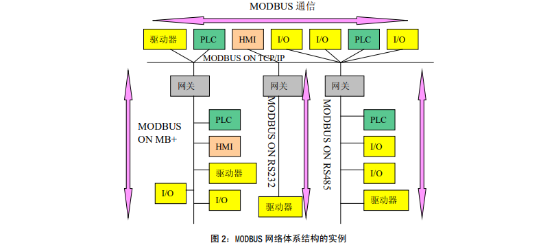
Every device (PLC, HMI, control panel, driver, motion control, input/output device) can use the MODBUS protocol to initiate remote operation.
The same communication is possible over MODBUS over serial links and Ethernet TCP/IP networks.
Some gateways allow communication between several buses or networks using the MODBUS protocol.
4 General description
4.1 Protocol description
The MODBUS protocol defines a simple protocol data unit (PDU) that is independent of the underlying communication layer.on a specific bus or network
The MODBUS protocol mapping can introduce some additional fields on the application data unit (ADU).
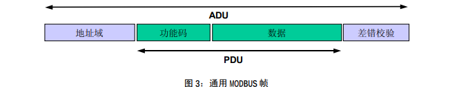
A client that initiates a MODBUS transaction creates a MODBUS application data unit. Function codes indicate to the server which operation will be performed.
The MODBUS protocol establishes a client-initiated request format.
Use one byte to encode the function code field of the MODBUS data unit. The valid codeword range is decimal 1-255 (128-255 are reserved for exception responses). When a message is sent from the client to the server device, the function code field tells the server what operation to perform.
Add sub-function codes to some function codes to define multiple operations.
The data field of the message sent from the client to the server device includes additional information, and the server uses this information to perform the operation defined by the function code. This field also includes discrete item and register addresses, the number of items processed, and the actual number of data bytes in the field.
In certain requests, the data field can be non-existent (0 length), in which case the server does not require any additional information. Function codes only describe operations.
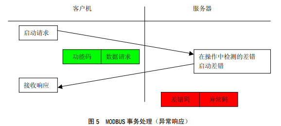
If no errors related to the requested MODBUS functionality occurred in a correctly received MODBUS ADU, the server-to-client response data field includes the request data. If an error occurs related to requesting MODBUS functionality, the field includes an exception code that the server application can use to determine the next operation to perform.
For example, a client can read the on/off status of a set of discrete outputs or inputs, or a client can read/write the data contents of a set of registers.
When the server responds to the client, it uses the function code field to indicate a normal (error-free) response or something went wrong (called an exception response). For a normal response, the server only responds to the original function code.
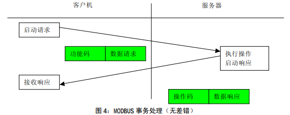
For an exception response, the server returns a code equal to the original function code and sets the most significant bit of the original function code to logic 1.
Comment: Timeouts need to be managed to explicitly wait for a reply that may not come.
The length constraint of the first MODBUS implementation on the serial link limits the MODBUS PDU size (maximum RS485ADU=256 bytes).
Therefore, for serial link communication, MODBUS PDU = 256 – server address (1 byte) – CRC (2 bytes) = 253 bytes.
thereby:
RS232 / RS485 ADU = 253 bytes Server address (1 byte) CRC (2 bytes) = 256 bytes.
TCP MODBUS ADU = 249 bytes MBAP (7 bytes) = 256 bytes.
The MODBUS protocol defines three types of PDUs. They are:
MODBUS request PDU, mb_req_pdu
MODBUS response PDU, mb_rsp_pdu
MODBUS exception response PDU, mb_excep_rsp_pdu
Define mb_req_pdu as: mb_req_pdu = { function_code, request_data}, where
function_code – [1 byte] MODBUS function code
request_data – [n bytes], this field is related to the function code and usually includes information such as variable references, variables, data offsets, sub-function codes, etc.
Define mb_rsp_pdu as:
mb_rsp_pdu = { function_code, response_ data}, where
function_code – [1 byte] MODBUS function code
response_data – [n bytes], this field is related to the function code and usually includes information such as variable references, variables, data offsets, sub-function codes, etc.
Define mb_excep_rsp_pdu as:
mb_excep_rsp_pdu = { function_code, request_data}, where
function_code – [1 byte] MODBUS function code 0x80
exception_code – [1 byte], MODBUS exception codes are defined in the table below.
4.2 Data encoding
MODBUS uses a ‘big-Endian’ representation of addresses and data items. This means that when multiple bytes are transmitted, the most significant bit is sent first.For example: register size value
16 – Bit 0x1234 The first byte sent is 0x12 then 0x34
Note: See [1] for more detailed information.
4.3 MODBUS data model
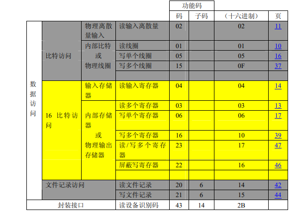
MODBUS is based on a series of data models on tables with different characteristics. The four basic forms are:
| basic form | Object type | access type | content |
| Discrete input | single bit | nur lesen | The I/O system provides this type of data |
| Coil | single bit | Lesen und Schreiben | Change this type of data through the application |
| Eingaberegister | 16-bit word | nur lesen | The I/O system provides this type of data |
| Bestandsregister | 16-bit word | Lesen und Schreiben | Change this type of data through the application |
The distinction between input and output and between bit-addressed and word-addressed data items does not imply any application operation. If this is the most natural explanation for the core of the suspect object, then this distinction is perfectly acceptable and commonplace, so that all four tables are considered to cover one another.
For any item in the basic table, the protocol allows 65536 data items to be selected individually, and read and write operations on those items are designed to span multiple consecutive data items up to the data size specification limit, which is consistent with the transaction processing function code related.
Obviously, all data processed via MODBUS must be placed in the device application memory. However, the physical address of the memory should not be confused with the data reference. The requirement is simply that the data reference is linked to a physical address.
The MODBUS logical reference number used in the MODBUS function code is an unsigned integer index starting from 0.
Examples of MODBUS model implementation
The following examples show two ways of structuring data in the device. There may be different structures, not all described in this document. Each device has its own data structure based on its application.
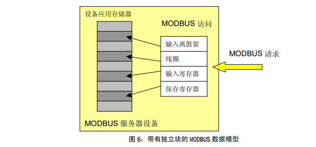
Example 1: Device with 4 independent blocks
The following example shows the data structure in a device that contains digital and analog quantities, inputs and outputs. Since the data in different blocks are not related, each block is independent of each other. Access each block according to different MODBUS function codes.
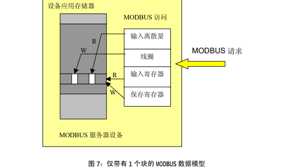
Example 2: Device with only 1 block
In this example, the device has only 1 data block. It is possible to obtain the same data via several MODBUS function codes, or via 16-bit access or 1 access bit.
4.4 Definition of MODBUS transaction processing
The following state diagram describes the general processing of MODBUS transactions on the server side.
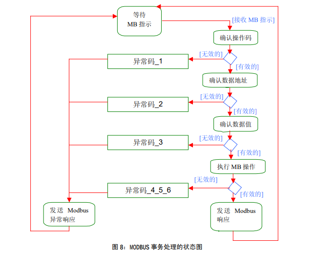
Once the server processes the request, it builds a MODBUS response using the appropriate MODBUS server transaction.
Depending on the processing results, two types of responses can be established:
● A positive MODBUS response:
● Response function code = Request function code
● A MODBUS exception response (see Section 6.14)
● Used to provide the client with information related to errors discovered during processing;
● Response function code = request function code 0x80;
● Provide an exception code to indicate the cause of the error.
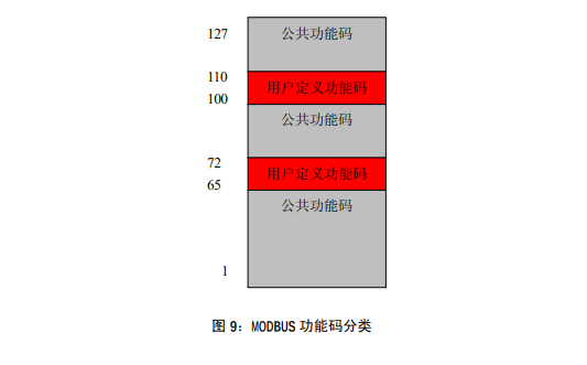
5 Function code classification
There are three types of MODBUS function codes. They are:
● Is a well-defined function code,
● Guaranteed to be unique,
● Die MODBUS-Organisation kann geändert werden,
● Öffentlich nachgewiesen,
● Konformitätstests verfügbar haben,
● Wie im MB IETF RFC gezeigt,
● Enthält definierte öffentliche zugewiesene Funktionscodes und nicht zugewiesene reservierte Funktionscodes für die zukünftige Verwendung.
Benutzerdefinierter Funktionscode
● Es gibt zwei Definitionsbereiche für benutzerdefinierte Funktionscodes, nämlich 65 bis 72 und dezimal 100 bis 110.
● Der Benutzer kann einen Funktionscode ohne Genehmigung der MODBUS-Organisation auswählen und implementieren
Es gibt keine Garantie, dass der gewählte Funktionscode eindeutig verwendet wird.
Wenn der Benutzer die Funktion als öffentlichen Funktionscode zurücksetzen möchte, muss er einen RFC initiieren, um die Änderung in die öffentliche Kategorie einzuführen und einen neuen öffentlichen Funktionscode zuzuweisen.
Funktionscode reservieren
● Funktionscodes, die von einigen Unternehmen für traditionelle Produkte verwendet werden und für den öffentlichen Gebrauch ungültig sind.
5.1 Definition der öffentlichen Funktionscodes
6 Beschreibung des Funktionscodes
6.1 01 (0x01) Spule lesen
Verwenden Sie diesen Funktionscode in einem entfernten Gerät, um den kontinuierlichen Status der Spule von 1 bis 2000 zu lesen. Die Anforderungs-PDU enthält die Startadresse, die erste angegebene Spulenadresse und die Spulennummer. Die Adressierung der Spule beginnt bei Null. Die Adressierung der Spulen 1-16 ist also 0-15.
Die Spule in der Antwortnachricht wird entsprechend jedem Bit des Datenfeldes in eine Spule unterteilt. Der angezeigte Status ist 1= EIN und 0= AUS. Das LSB (least significant bit) des ersten Datenbytes enthält den in der Abfrage adressierten Ausgang. Die anderen Coils folgen dieser Reihenfolge, bis zum High-End dieses Bytes und von Low zu High in den folgenden Bytes.
Ist die Anzahl der zurückgegebenen Ausgänge kein Vielfaches von acht, werden die verbleibenden Bits im letzten Datenbyte (bis zum höherwertigen Ende des Bytes) mit Nullen aufgefüllt. Das Feld Anzahl der Bytes gibt die vollständige Anzahl der Datenbytes an.
PDU anfordern
| Funktionscode | 1 Byte | 0x01 |
| Ausgangsadresse | 2 Bytes | 0x0000 bis 0xFFFF |
| Anzahl der Spulen | 2 Bytes | 1 bis 2000 (0x7D0) |
Antwort-PDU
| Funktionscode | 1 Byte | 0x01 |
| Anzahl der Bytes | 1 Byte | N* |
| Spulenstatus | N Bytes | n=N oder N 1 |
*N=Ausgangsmenge/8, wenn der Rest ungleich 0 ist, dann N = N 1
Fehler
| Funktionscode | 1 Byte | Funktionscode +0x80 |
| Ausnahmecode | 1 Byte | 01 oder 02 oder 03 oder 04 |
Dies ist ein Beispiel für eine Anfrage zum Lesen der diskreten Ausgänge 20-38:
| fragen Sie | Antwort |
| Domain-Name | (hexadezimal) | Domain-Name | (hexadezimal) |
| Funktion | 01 | Funktion | 01 |
| Startadresse Hallo | 00 | Anzahl der Bytes | 03 |
| Startadresse Lo | 13 | Status der Ausgänge 27-20 | CD |
| AusgabemengeHallo | 00 | Ausgangsstatus 35-28 | 6B |
| Output quantity Lo | 13 | Output status 38-36 | 05 |
Represent the status of output 27-20 as the hexadecimal byte value CD, or 1100 1101 in binary. Output 27 is the MSB of this byte and output 20 is the LSB.
Typically, the bits within a byte are represented with the MSB on the left and the LSB on the right. The output of the first byte is 27 to 20 from left to right. The output of the next byte is 35 to 28 from left to right. When bits are transmitted serially, from LSB to MSB: 20 . . . 27, 28 . . . 35, and so on.
In the last data byte, output status 38-36 is represented as a hexadecimal byte value of 05, or 0000 0101 in binary. Output 38 is the sixth bit position from the left, and output 36 is the LSB of this byte. Fill the five remaining high-order bits with zeros.
Note: Fill the five remaining bits (up to the high-order bit) with zeros.