In many real-time monitoring systems, it is often necessary to receive data from distant measurement and control points. How to reliably and quickly implement on-site data collection, remote data transmission and output control is a problem that these monitoring modules must solve. In the pursuit of low-cost modern design, many powerful and reliable microcontrollers have been produced. This article is a data acquisition module designed based on the C8051F021 microcontroller with complete functions and high cost performance.
1. Hardware design of module
1.1 Overall structure of hardware
The overall hardware structure block diagram of this module is shown in Figure 1.
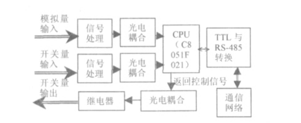
This module uses C8051F021 microcontroller as the core of the CPU control unit, and also includes multiple functions such as data acquisition, data storage, data communication, photoelectric coupling, and power-off protection. Since C8051F021 has relatively complete functions, the entire module is particularly simple, which not only reduces the size and power consumption of the module, greatly saves the cost of peripheral equipment, but also greatly improves the reliability and stability of the module.
1.2 Analog acquisition unit
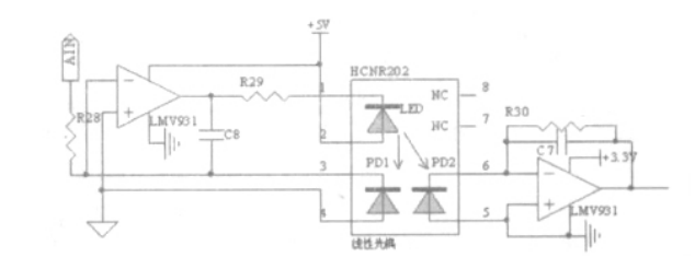
This module selects the ADC0 analog/digital conversion channel of C8051F021 as the acquisition channel of analog signals. For example, the temperature and humidity of the working environment can be collected in real time through temperature and humidity sensors. When the analog signal collected on site is transmitted to the ADC0 input channel of C8051F021, it will inevitably be interfered by external signals. From the perspective of anti-interference and ensuring the high linearity of the collected signal, a high linearity optocoupler HCNR201 is selected at the input end. The analog signal is isolated once, so that the useful signal is obtained more accurately and the interference component is removed. The circuit diagram is shown in Figure 2. The front-end operational amplifier LMV931 in the figure forms a negative feedback amplifier circuit to suppress changes in current in the LED; the back-end operational amplifier LMV931 forms an I/V conversion circuit. It can be seen from the figure that VOUT /VAIN=KR30 /R28, that is, the output voltage has a linear relationship with the input voltage and has nothing to do with the intensity of the LED output light. Adjust the voltage gain by adjusting the value of R30/R28. R29 is the current limiting resistor of the LED, and the two capacitors are used to improve the high-frequency characteristics of the circuit.
1.3 Switch signal acquisition unit
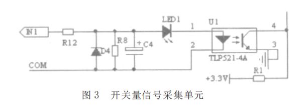
The acquisition unit is suitable for collecting signals with switching values, such as whether the circuit is powered or not, whether the water flow is passing or not, and other switching values. The circuit is shown in Figure 3. The acquisition unit is designed for 220V AC voltage input. Set to give no response when the input is approximately less than half of the AC peak value. In order to avoid interference caused by electrical characteristics and harsh working environment, photoelectric coupling is used to achieve primary electrical-to-optical-to-electrical conversion of the signal. Before entering the optocoupler, some of the spike pulses are filtered through the electrolytic capacitor. At the same time, this capacitor forms a discharge loop with the voltage dividing resistor. These measures effectively shield the interference during the signal transmission process. At the same time, LED work indicators are also installed, allowing users to see the working status of each channel at a glance.
1.4 Output control unit
This unit analyzes the data collected on site, and then the host computer staff or the microcontroller automatically gives the control output according to the preset feedback conditions to control the solid state relay JGX-1505FB with photoelectric isolation, and then drives the on-site control equipment. At the same time, LED work indicators are also installed, which can also clearly understand the working status of each channel.
1.5 RS-485 communication interface
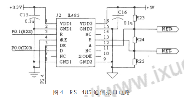
Judging from the analysis of many current solutions to medium and long-distance communication in microcontrollers, the RS-485 bus communication mode is widely used due to its simple structure, low price, appropriate communication distance and data transmission rate. Therefore, this module uses RS-485 communication and selects P0.0 and P0.1 of C8051F021 as the TX0 and RX0 of the serial port. From the perspective of reducing hardware peripherals, in the circuit, the self-isolated RS-485 interface chip IL485 is used. It uses dual power supplies. The end connected to the microcontroller is powered by 3.3V power supply, and the other end is powered by 5V power supply. The DE enable end of the RS485 interface chip is controlled by setting P2.4 of the microcontroller to 0 or 1, thereby controlling the transmission of communication data; its receive enable end/RE is grounded to remain low, that is, when the transmit enable is invalid, it is always Keep receiving. The specific circuit is shown in Figure 4. Compared with ordinary RS-485 chips, it can prevent high-voltage lightning strikes. For some sites with relatively harsh environments, it can be directly connected to the transmission line without any additional protection components.
2 module software design
The module software is written in assembly language and mainly consists of the main program module, data acquisition and processing module, communication module, data output control module, etc. The tasks of the main program include initialization of each programmable device, stack, various parameters, etc. After the initialization is completed, the interrupt is opened immediately, and the source of the interrupt is determined and the corresponding service module (such as data collection, data sending and receiving, etc.) is entered. After the service is completed, the system returns to the specified entry in the main program and waits for the next cycle. The data acquisition module generally works on site. Since the working environment on site is usually harsh and there is a lot of interference caused by various equipment, there are certain errors in the collected data. In addition to strengthening anti-interference measures on the hardware, in the software design Corresponding measures have also been taken. By analyzing the ways and causes of errors, the errors in the collected data are classified into gross errors, systematic errors and random errors, and corresponding processing strategies are adopted according to the characteristics of these three types of errors: First, de-extreme averaging filtering is used to eliminate coarse errors. The impact of errors and random errors, secondly, consider the impact of systematic errors caused by sensors and other components on the collected data, and form a table based on the correction values obtained from the system errors, and eliminate the systematic errors in the data by looking up the table. In addition, in order to ensure the reliability and stability of the module, other software functions such as power-down protection and system reset are also added.
3 module scalability and applications
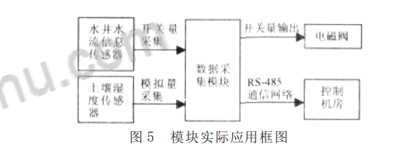
This article designs a data acquisition module with 4 analog inputs such as sensors, 4 switching inputs with photoelectric isolation, and relay output. This module selects C8051F021 as the core control unit of the CPU. C8051F021 has 64 pins. In this design, some of the pins are spare. These spare pins can be used to expand other functions according to actual needs. A typical application of this module is in the drip irrigation control system. The soil moisture is collected by the sensor and compared with the lower limit value of drip irrigation to obtain the command of watering or not. If it is a watering command, the watering out control command is executed and the water supply solenoid valve is driven through the relay. At the same time, 4-way switches collect water flow information to obtain feedback information on whether the irrigation is going smoothly. At the same time, the soil moisture sensor collects the moisture content of the soil in real time. When it exceeds the upper limit of drip irrigation, the output control command to close the solenoid valve will be executed. As shown in the system block diagram of Figure 5.
