1. Application block diagram
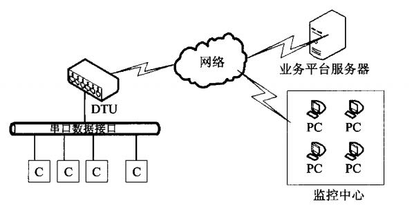
The DTU application framework diagram is shown in Figure 1. DTU communicates with node C through wired low-speed mode. Finally, DTU summarizes the data and sends it to the business platform server. The data uploaded by node C is called business data, and the DTU is only responsible for transmission without any processing; the data sent to the monitoring center is called control data, which mainly reports its own operating status. At the same time, the control center can also download the DTU. Control the command and let it execute the following commands, such as logging in again and restarting DTU, to achieve the monitoring effect.

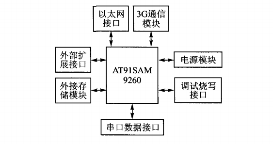
DTU structure diagram The DTU structure diagram is shown in Figure 2. This design uses Atmel’s AT91SAM9260, which is an industrial-grade microprocessor with an ARM926EJ-S core. It has a large number of peripheral interfaces and is a classic ARM9 processor can meet the processing needs of DTU. What’s especially important is that it supports the Linux operating system, which guarantees the stability of the entire DTU and improves the convenience of development.

The serial data interface is the RS-232 and RS-485 interfaces commonly used in industry and is the source of business data. The network interface is the commonly used RJ45 interface and 3G network interface. The 3G network uses China Telecom’s EVDO network, which is fast and stable and can meet the application of DTU in different occasions. In order to meet expansion needs, USB interfaces, microphone and earpiece interfaces are also reserved, so you can make calls with one click. In order for DTU to run the Linux operating system more perfectly, external SDRAM and Flash chips are connected to ensure sufficient memory and storage space.
2. Hardware design
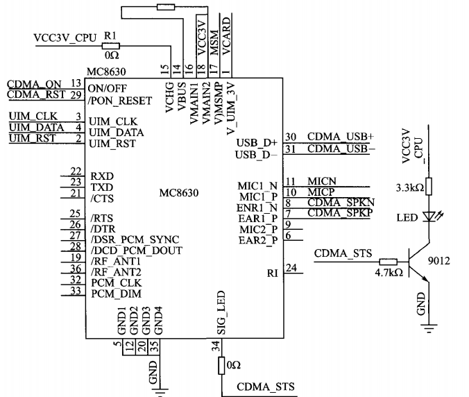
Figure 3 is a 3G module hardware connection diagram. This design uses the ZTE MC8830 module, which supports China Telecom’s EVDO network.
UIM CL.K, UIM_DATA and UIM RST are connected to the corresponding pins of the UIM card respectively. This circuit adopts a flexible method to control the switch of the module. R1 is a 0 Ω resistor. If the resistor is not welded, a low-level pulse lasting 1.5~2 s is output to the ON/OFF pin in the closed state to turn on the module. If such a pulse is received in the running state, the module will be turned off; if R1 is connected, the module will automatically turn on. Even if it is turned off through the ON/OFF pin, the module will still turn on automatically after shutdown []. In most cases, when the DTU is running, the module needs to be running, so R1 is welded on in practical applications. MC8630 uses USB communication with the chip to ensure that the 3G network speed is not limited. Therefore, the USB_D- and USB_D+ pins of the module are connected to the USB+ and USB- of AT91SAM9260. In order to ensure the normal operation of USB, 5 V needs to be added to the VBUS pin. voltage. In order to better interact with the outside world, MC8630.

The module sets aside a pin for controlling the LED – sIG-LED. When the module is powered on and working normally, this pin will flip the level once in about 3 seconds and cooperate with the LED circuit to achieve flashing; when the module dials up to send data to the Internet, time, the flip frequency will become 1S, so LED is a very good interactive interface. In order to protect this pin, an NPN transistor is used to assist in driving the LED to prevent excessive current from the LED lamp from damaging the module.
3. Software design
3.1 M2M protocol introduction M2M (Machine-to-Machine/Man) is a networked industry application and service with machine intelligent interaction as the core. It provides customers with comprehensive information solutions by embedding communication modules inside the machine and using network communication as an access method to meet customers’ various information needs. China Telecom’s MDMP (M2M protocol) is a very large and complex protocol. Its main features are as follows: ① The terminal number is uniquely bound to the IMSI number: each terminal logs in to the M2M control platform through a unique M2M card. ②Heartbeat mechanism: Periodically sends heartbeat messages to the platform to inform the platform of the terminal’s connection status.
Keywords: Internet of Things data transmission equipment