Foreword:
In order to solve the problem of diversification and complexity of analog quantity collection in engineering vehicles, a configurable analog quantity acquisition module is designed. This module is used in a universal vehicle controller based on Freescale’s 32-bit microprocessor MPC5646B. The hardware design scheme is introduced in detail and its configurable principle is explained. Using the MSComm control in VC6.0, a user configuration interface is designed in the host computer, and the configured parameters are stored in the Dataflash of the microcontroller. Finally, three types of analog quantities: voltage, current and resistance are collected and compensated, and the overall collection accuracy is controlled within 5‰. The measurement results show that the module is highly configurable and versatile and has good measurement accuracy.

sfondo:
As the requirements and dependence of automobiles on control systems increase, the A/D acquisition module has become an important part of the automobile controller. There are three main types of analog inputs in general engineering vehicles: resistance type (such as oil level sensor), current type (generally 4 to 20mA, such as pressure transmitter), and voltage type (such as battery voltage collection). However, due to different application scenarios, different engineering vehicles require different types and quantities of analog quantities to be collected. Therefore, the analog input module of the controller needs to have certain configurability before it can be applied to different engineering vehicles. For example, in a construction machinery system, 4 analog signals need to be collected, 2 of which are voltage signals, and 1 is current and resistance type. In addition, a system also has 4 analog signals, but they are all voltage signals. This Generally, you need to use function-customized controllers for the two systems respectively. However, if you add a configurable analog acquisition module to the controller, you only need to configure different functions in the software to meet the needs of the two systems at the same time. , which enhances the flexibility of the system.
The 16-channel configurable analog acquisition module designed in this article solves the above problems well. The A/D conversion channel of this module is based on the 12-bit successive approximation analog-to-digital converter (ADC) of the controller main chip MPC5646B, which is a freescale 32-bit Qoriva series microcontrollers are built using PowerArchitecture? technology and are suitable for automobiles and oriented to engines. Management applications, body control, gateway, security, chassis and driver information applications.
Hardware circuit design
(1) Principle of configurability

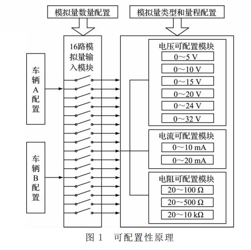
The principle of configurability is shown in Figure 1. This design is aimed at common analog quantities in engineering vehicles. The voltage type analog quantities are divided into 6 ranges: 0~5V, 0~10V, 0~15V, 0~20V, 0~24V, 0~32V. The current type analog quantities are The analog quantity is divided into 2 ranges: 0~10mA, 0~20mA. The resistance type analog quantity is divided into 3 ranges: 20~100Ω, 20~500Ω, 20Ω~10kΩ. In actual applications, different vehicles configure the 16 inputs in Figure 1 as the above three different types and different ranges of analog acquisition channels according to needs.
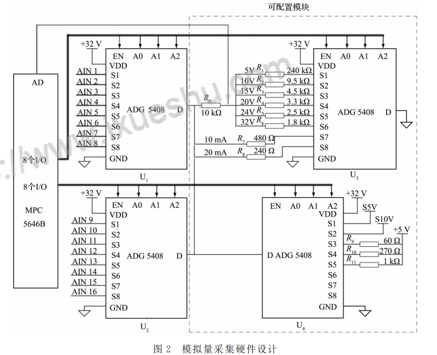
(2) The hardware design principle is shown in Figure 2. There are 16 analog acquisition channels AIN1~AIN16, which are cascaded through 2 multiplexers U1 and U2. U3 and U4 are configurable modules for analog measurement. Among them, S1~S6 of U3 correspond to the 6 ranges of voltage measurement, S7~S8 correspond to the 2 ranges of current measurement, and S3~S5 of U4 correspond to the 3 ranges of resistance measurement. The enable terminal EN of the multiplexer ADG5408 and the address lines A0, A1 and A2 are output by the I/O port of the main chip. The input analog quantity is input into a 12-bit A/D port of MPC5646B for conversion after conditioning.

(3) Analog multiplexing chip ADG5408 ADG5408 is a single-chip CMOS analog multiplexer from Analog Device Company, certified for automotive applications. Built-in 8 single channels, one of the 8 inputs is switched to the common output according to the address determined by the 3-bit binary address lines A0, A1 and A2. Powered by a 9-40V single power supply, the input signal range can be extended to the power supply voltage range. This design uses 32V power supply to meet the maximum voltage measurement of 32V. The on-resistance curve is very flat over the entire analog input range, with a low on-resistance of 13.5Ω. Very small channel leakage current, the maximum channel leakage at -40~+85°C is 4 nA, and the influence between channels is almost negligible.
(4) Introduction to the A/D module of the main chip. The A/D part of the MPC5646B includes 10-bit and 12-bit precision. The two modules are independently powered. The chip ADR02 is a 5V precision reference voltage source produced by the A/D company, which is A /D module provides 5V reference voltage [6]. There are 16 high-precision channels and 13 standard channels in the 12-bit A/D channel. Each channel has a dedicated conversion result register. In this design, the high-precision channel in the 12-bit A/D is used.
(5) Detailed explanation of circuit functions
①Voltage measurement function
In general engineering vehicles, the voltage can reach up to 32 V, and the ADC module of MPC5646B supplies 5V, so the voltage must be divided before it can be input to the A/D port. In Figure 2, S1~S6 of U3 are connected to 6 voltage dividing resistors R1~R6, and the voltage sampling is performed for 6 ranges: 0~5V, 0~10V, 0~15V, 0~20V, 0~24V, and 0~32V. The resistor is a high-precision low-temperature drift type [8]. The 10kΩ resistor R0 is a common voltage dividing resistor. After dividing the voltage, it is connected to the A/D port of MPC5646B. It can be configured to the corresponding range according to the voltage range that needs to be collected in the engineering vehicle. If the AIN1 channel of vehicle A needs to be configured with 0~20V, select the S1 channel of U1 and the S4 channel of U3.
②Current measurement function
The A/D port cannot directly measure current, so it must be converted into voltage through a resistor. As shown in Figure 2, S7 and S8 of U3 are connected to two resistors, corresponding to two current ranges of 0~20mA and 0~10mA. At this time, the voltage dividing resistor R0 when measuring voltage has a large resistance, so the shunting effect can be almost ignored, and it can be regarded as a wire when measuring current. If the AIN7 channel of vehicle B needs to be configured to 0~20mA, select the S7 channel of U1 and the S7 channel of U3.
③Resistance measurement function
Since resistance is a passive physical quantity, measuring resistance requires an internal power supply and a known resistor in series to divide the voltage. As shown in Figure 2, the S3, S4, and S5 channels of U4 are connected to 60Ω, 270Ω, and 1kΩ resistors, corresponding to the three measurement ranges of 20~100Ω, 20~500Ω, and 20~10kΩ respectively. If the AIN15 channel of vehicle C needs to be configured to 20~500Ω, select the S7 channel of U2 and the S4 channel of U4.
This article is reprinted on “Love Academics”. If it causes damage to your interests, please contact us to delete it!