With the continuous development of electronics, oscillator circuits have been widely used in various instruments and equipment as an extremely useful functional circuit, and then entered various fields such as wireless communications. Today, we will talk about the 555 oscillator using an LED flash circuit with a 555 oscillator.
What is a 555 oscillator
Simply put, a 555 oscillator is an integrated circuit capable of outputting a pulse signal at a specific frequency. The principle of the 555 oscillator is very simple but powerful. There are only 26 transistors inside, and the internal flip-flop is a type of digital circuit.
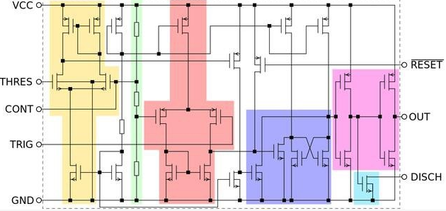
Internal structure: To understand the working principle of an integrated circuit, we must first understand its internal schematic diagram. The internal schematic diagram of the 555 oscillator is shown in the figure below.

There are not many integrated transistors inside the 555 oscillator, only 26. The A12 X chip used in the iPad Pro integrates more than 10 billion transistors, and even the A12 of the iPhone XS also integrates billions of transistors. Although they are both chips, they are similar in size. It can only be said that science and technology are advancing so fast!
Below is a simplified schematic of the 555 oscillator, the colored parts are modular and correspond to the comparators and flip-flops. The yellow triangle and pink triangle are the two comparators, and the purple triangle on the right is the RS flip-flop.
The green resistors on the left are three resistors with a resistance value of 5K, which is where the name 555 oscillator comes from. There is also an oscillator with a 556. What is the difference between the 556 and the 555? Do you think that besides the two 5K resistors, the other one is a 6K resistor?
Of course not, the 556 oscillator has 1 more than the 555 oscillator, but this 1 does not represent the 1K resistor, but the two 555 oscillator modules included in the 556. Such naming is indeed puzzling!
The figure below is a simplified diagram of each functional module inside the 555. Each pin definition has different effects.
Pin 1: Negative pole of power supply
Pin 8: Positive power supply
Pin 4: Reset pin, connect positive here
Pin 5: Discharge pin, connected to the negative pole through the capacitor
Pin 2 and Pin 6: Comparator control pins.These two pins are connected together to control the comparator to output high and low levels according to different voltages, and then control the flip-flop.
Pin 7: Use fixed wiring method to connect between R1 and R2
Pin 3: Pulse signal output pin, which is also a useful pin for us
How to control LED flash with 555 oscillator
The 555 can output over 200 milliamps, so it can drive a load, but some only output pulse signals with a few milliamps of current, so those 555 oscillators cannot drive a load. Connect the LED light to the OUT pin in series with a 1K resistor to limit the current.
We all know that the OUT pin of the 555 oscillator outputs a rectangular wave, but how do we know its frequency? It’s very simple. R1, R2 and C1 on the upper pin can calculate the output frequency of the OUT pin. The frequency of the rectangular wave is; f = 1.44/(R1 2R2) C1
As shown in the picture above: R1 = 100K, R2 =200K, C1 = 10uF
The output frequency of the rectangular wave f = 1.44 / (1000000 4000000) 10UF = 0.288HZ555
0.288 is the frequency, converted to period: 1 /0.288 = 3.4S, which to some extent indicates that the LED light changes state every 1.7S.
The 555 timer has the characteristics of low cost and reliable performance. It only needs to connect a few external resistors and capacitors to easily complete pulse generation and conversion circuits such as multivibrators, monostable triggers and Schmitt triggers. It is also often used as a timer in a wide range of instrumentation, household appliances, electronic measurement and automatic control. The above is the introduction and use of the 555 oscillator.Keywords: network IO controller