
Universal Asynchronous Receiver/Transmitter, often called UART, is an asynchronous receiver/transmitter.
First, let’s introduce the following synchronous and asynchronous communication. Synchronous means that after the sender sends the data, it waits for the receiver to send back a response before sending the next data packet; asynchronous means that after the sender sends the data, it waits for the receiver to send it. The party sends back a response and then sends the communication method of the next data packet. In other words, synchronous communication is a blocking method, and asynchronous communication is a non-blocking method. Among common communication bus protocols, I2C and SPI belong to synchronous communication while UART belongs to asynchronous communication. The two parties in synchronous communication must first establish synchronization, that is, the clocks of both parties must be adjusted to the same frequency, and the sender and receiver must continuously send and receive a continuous synchronization bit stream. When sending characters in asynchronous communication, the sending end can start sending characters at any time. Therefore, in UART communication, the data start bit and stop bit are essential.
hardware layer
The commonly used RS-232 standard will not be explained in detail here. The main thing is that the Tx line and Rx line of the corresponding device must be correctly matched.
Protocol layer
In the protocol layer, the content of the data packet is stipulated, which consists of a start bit, body data, check bit and stop bit. The data packet format of both communicating parties must be agreed upon to send and receive data normally.
Baud rate: Since there is no clock signal in asynchronous communication, the two communication devices need to agree on the baud rate. Common ones are 4800, 9600, 115200, etc.
Start and stop signals of communication: A data packet in serial communication starts from the start signal and ends with the stop signal. The start signal of the data packet is represented by a logic 0 data bit, while the stop signal of the data packet can be represented by 0.5, 1, 1.5 or 2 logic 1 data bits, as long as both parties agree.
Valid data: Immediately after the starting bit of the data packet is the main data content to be transmitted, also called valid data. The length of valid data is often agreed to be 8 or 9 bits long.
Data check: After the valid data, there is an optional data check digit. Since data communication is relatively susceptible to external interference, causing deviations in the transmitted data, a check bit can be added to the transmission process to solve this problem. Verification methods include odd parity (odd), even parity (even), 0 parity (space), 1 parity (mark) and no parity (noparity).
Odd parity requires that the number of “1”s in the valid data and check bits is an odd number. For example, an 8-bit long valid data is: 01101001. At this time, there are a total of 4 “1”s. In order to achieve the odd parity effect, the parity check The parity bit is “1”, and the final transmitted data will be 8 bits of valid data plus 1 bit of check bit, a total of 9 bits. The requirements for even parity and odd parity are exactly the opposite. The number of “1”s in the frame data and parity bits is required to be an even number. For example, data frame: 11001010. At this time, the number of “1”s in the data frame is 4, so it is even. The check digit is “0”. 0 parity means that no matter what the content of the valid data is, the check digit is always “0”, 1 parity means the check digit is always “1”.
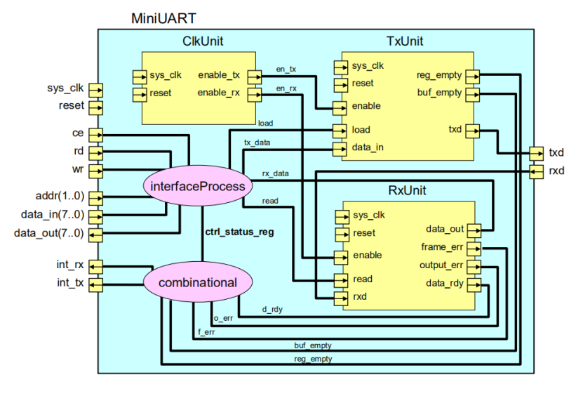
UART functional block diagram analysis
This picture is a module diagram of UART modeling using System C when I was in school. For the interface part, the important ones are Tx, Rx data output, receiving interface, and clk provides the initial clock signal of the baud rate generation module. Regarding the controller part, logic circuits are used here to implement specific control of output/reception enable, device enable, etc.
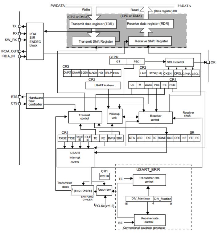
On current microcontrollers, the digital circuit control part has been encapsulated, and now you only need to operate the corresponding bits of the corresponding register to control the UART. Taking the chip STM32F411 in hand as an example, the following figure is the UART block diagram:
Baud rate generation module:
The USART’s transmitter and receiver use the same baud rate.There is the following calculation formula
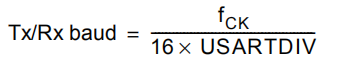
Among them, fck is the USART clock, and USARTDIV is an unsigned fixed-point number stored in the baud rate register (USART_BRR). The DIV_Mantissa[11:0] bits define the integer part of USARTDIV, and the DIV_Fraction[3:0] bits define the fractional part of USARTDIV.
For example: DIV_Mantissa=24 (0x18), DIV_Fraction=10 (0x0A), then the USART_BRR value is 0x18A; then the decimal digits of USARTDIV are 10/16=0.625; the integer digits are 24, and the final value of USARTDIV is 24.625.
Common values for baud rate are 2400, 9600, 19200, and 115200. The following uses an example to explain how to set the register value to obtain the baud rate value. We know that USART1 uses the APB2 bus clock, which can reach up to 72MHz, and the other USARTs have a maximum frequency of 36MHz. We choose USART1 as an example to explain, that is, fck=72MHz. In order to get the baud rate of 115200bps, at this time: 115200=72000000/(16*USARTDIV), the solution is USARTDIV=39.0625, it can be calculated that DIV_Fraction=0.0625*16=1=0x01, DIV_Mantissa=39=0x27, that is, USART_BRR should be set The value is 0x171.
Data register:
Only the lower 9 bits of the UART data register (USART_DR) are valid, and whether the 9th bit data is valid depends on the M bit setting of the UART control register 1 (USART_CR1). When the M bit is 0, it means that the 8-bit data word length is A value of 1 represents a 9-bit data word length, and we generally use an 8-bit data word length.
USART_DR contains sent data or received data. USART_DR actually contains two registers, a writable TDR specially used for sending, and a readable RDR specially used for receiving. When performing a sending operation, writing data to USART_DR will automatically be stored in TDR; when performing a reading operation, reading data to USART_DR will automatically extract RDR data.
Both TDR and RDR are between the system bus and the shift register. Serial communication is transmitted bit by bit. When sending, the TDR content is transferred to the sending shift register, and then each bit of the shift register data is sent out. When receiving, each received bit is sequentially stored in the receiving shift register. register and then transferred to RDR.
UART supports DMA transmission, which can realize high-speed data transmission (without going through the CPU). To enable the DMA function of UART, you need to set the DMAT bit of the USART_CR1 register to 1.
Controller:
UART has a transmitter that specifically controls sending, a receiver that controls receiving, as well as a wake-up unit, interrupt control, etc. Before using UART, you need to enable UART by setting the UE bit of the USART_CR1 register to 1. The UE bit is used to turn on the clock supplied to the serial port. The length of the data sent or received can be 8 or 9 bits, controlled by the M bit of USARTT_CR1.
1) Transmitter
When the transmission enable bit TE of the USART_CR1 register is set to 1, data transmission is started, and the data in the transmission shift register will be output on the TX pin, with the low bit first and the high bit last.
A character frame transmission requires three parts: start bit, data frame, and stop bit. The start bit is the low level of a bit period, and the bit period is the time occupied by each bit; the data frame is the 8 or 9-bit data we want to send, and the data is transmitted starting from the lowest bit; the stop bit is a certain time period high level.
The length of stop bits can be controlled by the STOP[1:0] bits of UART control register 2 (USART_CR2), and 0.5, 1, 1.5, and 2 stop bits are optional. By default, 1 stop bit is used. 2 stop bits are available for normal USART mode, single wire mode and modem mode. 0.5 and 1.5 stop bits are used in smart card mode.
When the transmit enable bit TE is set to 1, the transmitter starts to send an idle frame (a high level of data frame length), and then the data to be sent can be written to the USART_DR register. After writing the last data, you need to wait for the TC bit of the UART status register (USART_SR) to be 1, indicating that the data transfer is completed. If the TCIE bit of the USART_CR1 register is set to 1, an interrupt is generated.
When sending data, several important flags are as follows:
TE: Transmit enable.
TXE: The transmit register is empty, used when sending a single byte.
TC: Transmission completed, used when sending multiple bytes of data.
TXIE: Transmit completion interrupt enable.
2) Receiver
Set the RE bit of the CR1 register to 1 to enable USART reception, causing the receiver to start searching for the start bit on the RX line. After determining the start bit, the data is stored in the receiving shift register according to the RX line level state. After the reception is completed, the data in the receiving shift register is moved to the PDR, and the RXNE position of the USART_SR register is changed. An interrupt can be generated if RXNEIE in the USART_CR2 register is set to 1.
When receiving data, several important flags are as follows:
RE: receive enable.
RXNE: Read data register is not empty.
RXNEIE: Transmit completion interrupt enable.
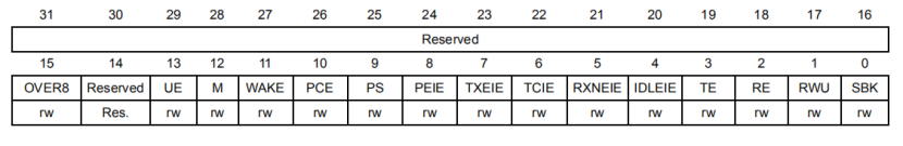
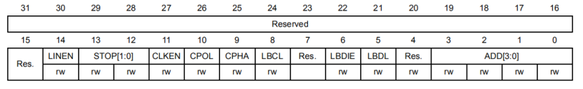
USART_CR1 register:
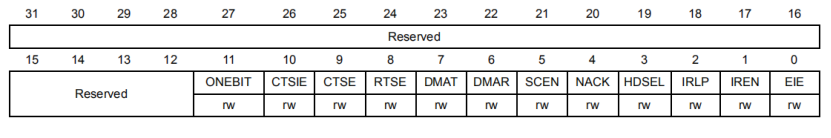
USART_CR2 register:
USART_CR3 register:
Trefwoorden: serial port module