
ZHC2931 is an upgraded version of a multi-functional integrated controller based on Internet of Things technology. Users of the Internet of Things control system implemented through this controller can realize remote monitoring of terminal equipment. Provides 1 serial port (RS485/RS232), 2 DI, 1 DO and 1 AI interface, supporting local logic processing operations, automatic collection and active reporting, Modbus RTU/TCP adaptation, automatic calibration threshold reporting, and configuration software docking, dry and wet node IO detection and other special functions, supporting one -to-one and many-to-one networks. Scope of application: Internet of Things control, industrial automation monitoring, university laboratory data monitoring; field industrial site data monitoring; field agricultural monitoring point (greenhouse, etc.) data monitoring; building intelligent control; street light remote switch control cabinet.
Características do produto:
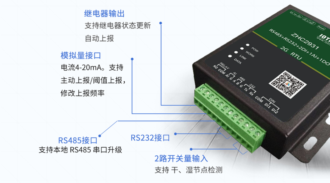
◆Support 1 relay output
◆ Support 2 DI (dry/wet node) inputs
◆ Support 1 analog (current) input
◆ Supports 8 conditional control instructions, making control more convenient
◆ Provide 1 serial port (RS485/RS232)
◆Support serial heartbeat package
◆ Supports multiple function codes: 01, 02, 03, 04, 05, 06, 0F, 10
◆ Support setting the direction of active data reporting
◆ Support TCP_Client, HTTP_Client
◆ Supports two working modes: host mode and slave mode. The host mode supports cascading multiple Modbus devices
◆ Compatible with Modbus RTU/TCP
◆ Support cloud forwarding and cloud networking
◆ Support local upgrade and remote upgrade
◆ Support hardware watchdog
◆Multiple indicator lights show working status
◆ Support domain name address resolution
◆ Support setting APN
◆ Support signal query
◆Support SIM card number query
◆ Support heartbeat package
◆ Support registration packages in any format to ensure the legality and uniqueness of device identity
◆ Provide one switching output
◆ The relay adopts photoelectric isolation
◆ The relay retains the long-open and long-closed state
◆Support timing flip of relay status
◆ Support setting relay start status
other instructions:
In view of the node monitoring and status switching functions required for on-site switch cabinet automation control, a remote controller based on Modbus-RTU is designed with the PIC microcontroller as the control core. The remote controller integrates the Modbus communication protocol, has device address management, communication parameter configuration, switch collection and control functions, and can interconnect with the downstream RS485 interface of the main controller such as the data collection gateway through the RS485 bus. Through practice verification, the remote controller can reliably realize the control and monitoring of on-site switches of the air conditioning system, with low implementation cost and reliable operation.
1 Introduction Modbus protocol is a bus protocol launched by Modicon Company and truly used in industrial fields [1]. Through this protocol, reliable communication between controllers and between controllers and other devices can be achieved through the communication network. Modbus is an application layer message transmission protocol on layer 7 of the OSI model. It can provide client/server communication between devices on different types of buses.
When communicating on the bus, in the Modbus protocol RTU mode, every 8-bit byte in the message is divided into two 4-bit hexadecimal characters. The main advantage of this mode is that the transmission density at the same baud rate is higher than ASCII mode[3]. On the RS458 bus, the Modbus protocol can realize remote communication from tens of meters to thousands of meters with the balanced transmission, differential reception and common-mode interference suppression capabilities used in RS-485 [4-5] . The designed remote controller uses Microchip’s 8-bit microcontroller as the core device and uses RS458 with isolation function as the communication bus. It has the ability to collect 12-bit status quantities and control 4-bit switching quantities. 2 Controller Hardware Design The The overall design of the remote controller based on PIC16F73 microcontroller is shown in Figure 1.
The PIC16F73 microcontroller has rich on-chip resources, with 22 GPIO interfaces, 3 timers, 11 interrupts and 1 AUSART universal serial port and other peripherals; it has 4K×14-bit FLASH memory and 192 bytes of RAM memory; operating temperature Wide, strong anti-interference ability, very suitable for industrial site use. In particular, it uses a high-performance RISC instruction set, has high execution efficiency, convenient and flexible programming, and provides a very convenient solution for small control systems [6-7 ]. Figure 1 Overall block diagram of remote controller hardware The remote controller uses 28-pin PIC16F73-I/SP, and a total of 4 channels of status quantity output control, 12 channels of status quantity acquisition input and 1 half-duplex RS485 interface are designed. In order to realize the protection function of the controller port, the 12-channel state quantity acquisition input interface is equipped with an optocoupler for isolation; the 4-channel switch output is realized by a relay; at the same time, it adopts a 2.5k V voltage isolation capability and ±15KV ESD protection The isolated RS-485 transceiver ADM2587E implements a high-speed RS485 communication interface [8]. The entire remote controller PCB circuit is shown in Figure 2. Figure 2 Remote controller PCB circuit (Top) Figure 3 Remote control module status control output circuit Figure 3 shows the output interface circuit of the controller, in which the IO port of the PIC microcontroller directly drives the TLP781 isolation optocoupler to control the passage of the relay working coil. Power off , thereby realizing the opening and closing operation of the status output. Figure 4 shows the principle design of one of the status quantity acquisition DI ports of the controller.
Figure 4 State quantity acquisition circuit with isolation protection The acquisition circuit uses optocoupler devices to achieve isolation between the input part and the main MCU to protect the safety of the core devices; at the same time, the input port power supply HVCC=24V, first passes through Q2/Z1/R17 The linear voltage stabilizing circuit is composed of a linear voltage stabilizing circuit to realize independent voltage stabilization power supply for each DI port; in addition, the TVS transient suppression diode SMBJ26A can reduce the impact of unexpected high voltage. 3 Controller software design The remote controller software adopts the front-end and back-end system mode. The foreground program is an infinite polling loop, and its overall design is shown in Figure 5.
Figure 5 Remote controller front-end software flow chart The front-end program mainly monitors the level status of 12 channels of DI and the byte receiving flag of UART. The background software of the controller mainly includes the monitoring process of 12 IO levels for status quantity collection, the status quantity output control process of 4 output IO ports, the Modbus-RTU protocol processing process, and UART serial port reception and UART serial port transmission, a total of 5 Task.
Figure 6 shows the process of sending and receiving UART data frames. Considering the fast and efficient performance of PIC microcontroller instruction cycle of 200ns, in order to increase the anti-interference ability of the system, the UART serial port also uses polling flag bit mode to confirm the sending and receiving of data.
When the serial port UART receives the complete data frame structure, the background program will enter the Modbus-RTU protocol processing flow to parse, execute and respond to the protocol frame. (a) Transmission of UART data frame (b) Polling reception of UART data frame Figure 6 Sending and receiving process of UART data frame 4 Controller Modbus protocol design Modbus protocol is a request/response protocol that can provide function codes corresponding to the protocol frame stipulated.
Keywords: dtu