
In industrial networking control, power conditioning, and point-to-point communication applications between computers, data is sent on the serial communication bus for various types of physical networks, such as RS232, RS485, and controller area networks. Each interconnected system typically has its own power supply, and systems are often far apart, so galvanic isolation is often required to break ground loops, protect the system from high-voltage transients, and reduce signal distortion.
isolation
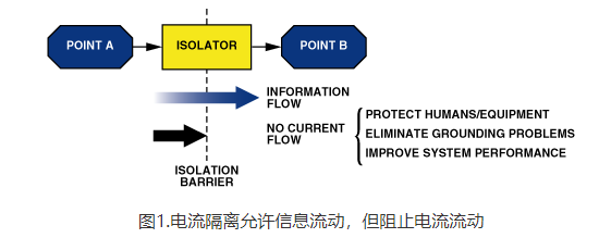
Transformers, coupling capacitors, and optocouplers (now called i-couplers) are typical methods of providing galvanic isolation, preventing current from flowing between two points while allowing data to pass through unhindered (Figure 1). Isolation is used to protect against high voltages or currents caused by line surges or ground loops, which can occur in any system with multiple paths to ground. System grounds separated by long cables will not be at the same potential, so ground current will flow between the two systems. Without isolation, this current can introduce noise, degrade measurement quality or even destroy system components.
Currents coupled into long cables in industrial environments through the turning on and off of motors, electrostatic discharge (ESD), or nearby lightning strikes can cause rapid changes in ground potential, often as high as hundreds or thousands of volts. When this happens, the logic level switching signal expected by the remote system will be superimposed on a high voltage relative to its local ground. Without isolation, this voltage could disrupt the signal or damage the system. Grounding all devices connected to the bus protects the system from this damaging energy , and isolating these devices prevents ground loops and surges.
To completely isolate the system, all signal lines and power supplies must be isolated. Isolated DC-DC converters provide power isolation, while iCoupler digital isolators provide signal isolation.
coupler technology
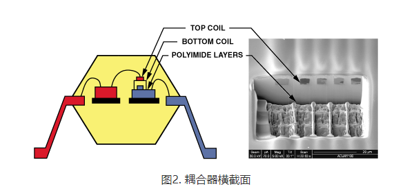
In contrast to the photodiodes used in EDs and optocouplers, coupler isolators are based on chip-scale transformer magnetic couplers (Figure 2). Planar transformers use a CMOS metal layer along with a gold layer placed above a passivation layer. A high-breakdown polyimide layer beneath the gold layer isolates the top transformer coil from the bottom. High-speed CMOS circuitry connected to the top and bottom coils provides the interface between each transformer and its external signals. Wafer-level processing provides a low-cost method to integrate multiple isolation channels as well as other semiconductor functions in a single package. I-coupler technology eliminates the uncertain current transfer ratios, nonlinear transfer functions, and drift (over time and temperature) associated with optocouplers; reduces power consumption by up to 90%; requires no external drivers or discrete devices.
Circuitry on the primary side of the transformer encodes the input logic transitions into 1 ns pulses, which are then coupled through the transformer. As shown in Figure 3, the circuitry on the secondary side detects them and recreates the input signal, and the refresh circuitry on the input side ensures that the output state matches the input state even if there is no input transition. This is important for power-up conditions and input waveforms at low data rates or constant DC input.
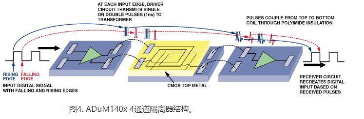
Because the purpose of an i-coupler product is to isolate the input from the output, the circuitry on one side of the transformer must be contained on a separate chip from the circuitry on the second side of the transformer. The transformer itself can be placed on either chip, or it can be placed on a third chip, such as the ADuM140x shown in Figure 4. The entire chipset is assembled in a standard plastic package, similar to those used for various semiconductor devices.
A novel feature of iCoupler devices is their ability to combine transmit and receive channels in the same package. The I-coupling transformer itself is bidirectional, so signals can go in either direction as long as the appropriate circuitry is present on each side of the transformer . In this way, multi-channel isolators are provided with multiple transmit/receive channel configurations.
serial communication bus
The RS-232 (EIA232) and RS-485 (EIA/TIA485) specifications define only the physical layer, allowing users or other standards that specify their use in the physical layer to define signaling protocols. On the other hand, CAN bus defines the physical layer and data link layer.
RS-232: The RS-232 bus standard is one of the most popular serial communication buses and was originally specified in 1962 for communication between computers and modems. Its simplicity, flexibility, and long history of successful use are still widely used as inter- system communication links, which are the reasons for its continued popularity. Designed for point-to-point communications, it uses two dedicated unbalanced single-ended lines along with a ground-referenced signal to provide full-duplex communications.
Data rates are limited to 20 kbps, or 64 kbps in low-voltage variations. The 2500-pF maximum load capacitance and 3kohm to 7kohm load impedance limit the maximum practical cable length to about 16 meters. RS-232 specifies a driver output level of –5 V to –15 V for logic 1, a driver output level of 5 V to –15 V for logic 0, and a receiver input level of –3 V to –15 V for logic 1. , while logic 3 is 3V. Logic 0 is 15V. Voltages between –3 V and 3 V are undefined. The wide voltage swing and uncertainty region ensure high noise immunity and allow effective signal levels to be received over longer cables.
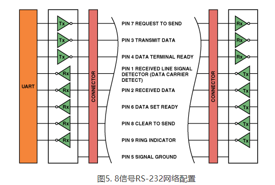
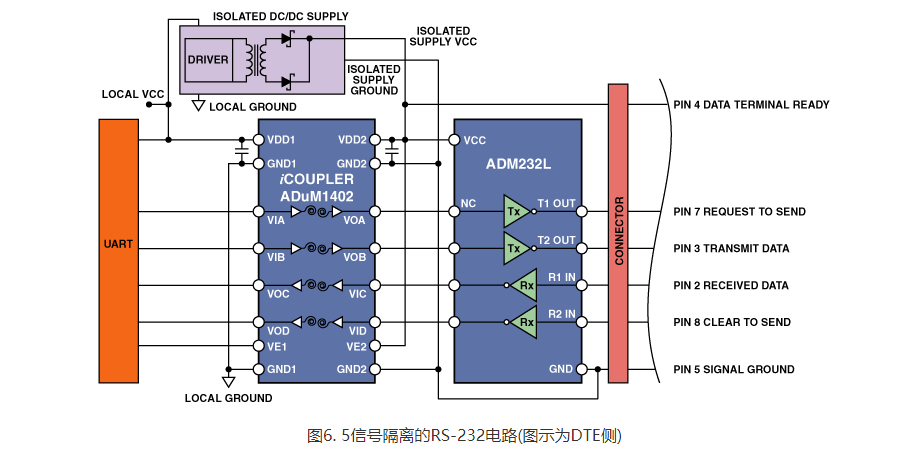
The RS-232 specification defines the pinout for a 25-pin D-type connector with 20 signal lines, but more commonly is a 9-pin connector with 8 signal lines, as shown in Figure 5. One wire is used in each direction for data transmission; the remaining wires are designated for the communication protocol. At its simplest, RS-232 only requires three wires: Tx (transmit data), Rx (receive data), and GND (ground). A protective ground for equipment safety is defined in the 25-pin connector. This wire is typically connected to power ground or chassis ground and should not be connected to signal ground or between systems.
The RS-232 standard divides equipment into two categories: DCE (data communications equipment) and DTE (data terminal equipment). These names are a legacy of its computer and modem heritage. Now, these terms only define which wires are connected as inputs and which wires are connected as outputs.
RS-232 is often used to connect multiple systems, so isolation between each system and the bus is critical. Digital isolators do not support the RS232 standard and therefore cannot be used between the transceiver and the cable; instead they are used between the transceiver and the local system. The system side of the transceiver typically connects to a universal asynchronous receiver/transmitter (UART) or processor using 0 V to 3 V or 0 V to 5 V logic levels. Because the i’s input and output circuit coupler isolators are electrically isolated from each other, they can be placed between the UART and the transceiver, which is an easy way to isolate the system from the cable. To complete the isolation, an isolated DC-DC converter is used to power the isolator and transceiver. The The combination of the ADuM1402 I-coupler digital isolator, ADM232L RS-232 transceiver, and isolated power supply, as shown in Figure 6, avoids ground loops and provides effective protection against surge damage.
RS-485: The RS-485 standard is specified to drive up to 32 pairs of drivers and receivers. Its versatility and ability to drive cables up to 4000 meters make it popular in a wide range of applications, especially in interconnection systems over very long distances. RS-485 communication is used in both Small Computer System Interface (SCSI) and PROFIBUS protocols.
Available cable lengths depend on data speed requirements, with speed/length combinations ranging from 200 kbps at 1200 meters to 12 Mbps at 100 meters. Using balanced differential signaling, the RS-485 driver sends data over two output lines. The receiver determines the logic state by comparing the two signals. A voltage drop greater than 200 mV provides valid logic levels. Differential amplifiers in the driver and receiver control the current flow between the signal lines. It has higher noise immunity compared to single-ended solutions such as RS- 232.
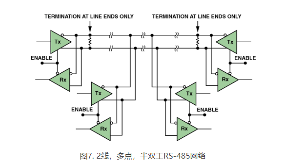
An enable function allows drivers to be placed in a high-impedance state; therefore, multiple drivers can share a bus without contention. This software protocol defines a bus arbiter that keeps all but one driver inactive at all times and allows up to 32 drivers to share the line. A half-duplex 2-wire bidirectional configuration is shown in Figure 7. Each node contains a driver and receiver, all sharing the same 2-wire twisted pair cable. While this simplifies installation and reduces costs, it limits maximum throughput . A 4-wire full-duplex configuration (using one node as the master and the remaining nodes as slaves) is more complex but provides higher data rates.
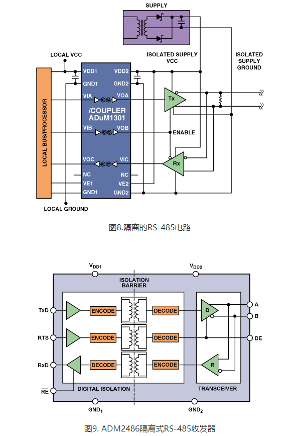
Since RS-485 is often used to connect multiple systems, isolation between each system and the bus is critical. Like RS-232, digital isolators do not support the RS-485 standard and therefore cannot be used between the transceiver and the cable. Instead , they are used between the transceiver and the local system. The system side of the transceiver is usually connected to a local bus or processor. Since the input and output circuits of an i-coupler isolator are electrically isolated from each other, inserting one between the processor and transceiver is an easy way to isolate the system from the cable. To complete the isolation, an isolated DC-DC converter is used to power the isolator and transceiver. The combination of the ADuM1301 i coupler digital isolator and isolated power supply shown in Figure 8 eliminates ground loops and provides effective protection against surge damage.
CAN Bus: Originally developed for automotive applications, the CAN bus standard specifies a 2-wire serial communication protocol that allows data rates up to 1 Mbps, up to 30 nodes, and a maximum cable length of 40 meters. It transmits asynchronous data in the form of frames that include start and stop bits, arbitration fields, control fields, cyclic redundancy check (CRC) fields, and acknowledgment fields. Each node can listen and transmit at the same time, so one of the protocol’s most important features is its lossless bit arbitration, which ensures no data is lost. Each node transmits a primary Start of Message (SOM) bit at the beginning of each message. Other nodes will see this activity and will not attempt to start transmission until the message is complete. Next, the 11-bit or 29-bit arbitration field is sent. Also called an identifier, this field prioritizes messages sent on the bus. The highest priority node always controls the bus while lower priority nodes wait. This lossless arbitration ensures that the highest priority messages always get through.
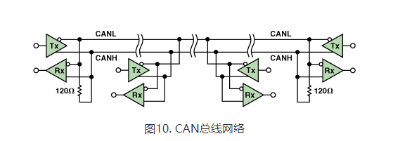
As shown in Figure 10, the CAN bus uses a balanced 2-wire differential interface that typically operates at 3 V or 5V. Non-return-to-zero (NRZ) encoding is used to ensure compact messages with a minimum number of messages. transition and high noise immunity. The CAN bus transceiver uses a pair of open-drain devices to create a differential signal from CANH (V CC – 0.9 V) to CANL (1.5 V). When driven, the transmitter produces a dominant signal that represents a logic low level. When no transmitter is driven, the pull-up resistor sets the bus to V CC /2, producing a recessive signal that represents a logic high. A backup control puts the transceiver into a low-power mode. The low -power receiver remains active in standby mode, monitors bus status changes, and signals the controller to activate the local node when activity is detected.
Like RS-232 and RS-485, digital isolators do not support the CAN bus standard and therefore cannot be used between the transceiver and the cable. Instead, use standard 3V or 5V logic levels between the transceiver and the local CAN controller. Because the input and output circuits of an i-coupler isolator are electrically isolated from each other, a simple way to isolate a system from cables is to insert an isolator between the processor and transceiver. To complete the isolation, an isolated DC-DC converter is used to power the isolator and transceiver. The combination of i-Coupler digital isolators and isolated power supplies (shown in Figure 11) eliminates ground loops and provides effective protection against surge damage.
Keywords: DTU data transparent transmission