Introduction:
Usually the parameters we see in the computer terminal screen: voltage, current, frequency, etc. are all digital signals. To convert the basic parameters into digital signals requires a complex process. This process is referred to as the analog channel. This article will become The impact of transmitter collection of basic parameters and analog transmission on digital terminal display is briefly analyzed, and the relationship between the two is analyzed, and the practical significance of the two in production operation is analyzed. As the main interface for centralized control operation of thermal power plants, DCS has become a control system widely adopted by thermal power plants that integrates monitoring, alarming, accident handling, and automatic control due to its stability, plasticity, operability, and economy. mode, and digital signals are the basis of DCS control. If the screen data display is inaccurate, it will bring great difficulties to the operation control. The task of the analog input channel is to convert the basic parameters collected by the transmitter such as temperature, pressure, current and other signals through the signal conditioning circuit, select multiple analog switches, and amplify the preamplifier to the range of the A/D converter. Sample and hold, A/D conversion, interface logic judgment, and finally conversion into a digital signal for display. This is the overall process of the entire analog channel. This article will start with the transmitter, select the voltage transmitter, the simplest type of transmitter, and analyze the impact on the analog channel based on its abnormal operation.
1 Principle of voltage transmitter
AC voltage transmitter is composed of voltage transformer, precision rectifier filter, and vi conversion circuit. The voltage transformer converts the AC voltage from 0v to 100v into the required AC voltage signal. The precision rectifier circuit amplifies and rectifies the AC voltage signal into a relatively stable DC voltage. Afterwards, the vi converter converts the stable DC voltage signal into a constant proportional current output. The ultimate goal is to convert AC power with an effective value of 0v ~ 100v into a DC current output of 4ma ~ 20ma (≤ 200Ω load).
2 Analysis of factors affecting AC voltage transmitter output
In the power production process, there are a variety of measurement, monitoring, control and other instruments, transmitters, and operating mechanisms. Due to differences in voltage levels, frequencies, signal strengths, etc., varying degrees of interference will occur during operation. Sometimes, interference may occur. Will cause distortion of measurement data. Another factor that affects the error of each meter is the ground current. In order to ensure safe operation, many equipment require shell protection and grounding. Since the ground point of each equipment has different ground reference potential, this will inevitably cause ground circulation to flow through transmitters and other instruments. between, affecting the measurement results.
3 solutions
In order to solve the problem of abnormal operation of the transmitter due to local interference of equipment and the influence of ground circulation, resulting in inaccurate digital signal indication after the analog channel, the power plant must take corresponding protective measures to avoid distortion of the computer-side digital signal due to interference. . The main factors that affect interference are the following: interference sources, induction sources, and coupling paths. When designing and constructing a power plant, it is obviously unrealistic to consider arranging various equipment, meters, and transmission mechanisms separately due to external interference factors without considering the actual needs of production. Therefore, separate layout measures for interference sources and induction sources cannot be implemented. We can only think of ways to make a fuss from the coupling path.
3.1 Keep transmitters and instruments at equal potentials
The specific layout is to optimize the grounding system of the entire factory, and use the same grounding point layout for components that are particularly susceptible to external disturbances from ground circulation to ensure equal ground potentials and eliminate circulation currents. For example, various meters in the protection screen of the generator-transformer unit are grounded in this way to avoid influence.
3.2 Minimize or no grounding
This method is of little significance in practical applications, because equipment protective grounding and shielding grounding have their own roles, and it is obviously unrealistic to cancel grounding due to fear of errors caused by ground circulation. Moreover, many equipment may be corroded and grounded due to external environment and other factors. It is unrealistic to not be grounded at all from the perspective of the external environment.
3.3 Use signal isolator
Use a signal isolator, that is, use the signal conditioning mode mentioned in the introduction of the article, to disconnect the external ground current loop, thereby eliminating the impact of ground current on the transmission effect of the transmitter. In addition, the signal isolator has multiple channels and interfaces, and also indirectly plays the role of signal conversion and distribution, interface conversion, etc., making the entire analog channel operation mode more flexible, economical and reliable. The existence of the signal isolator is also used to limit the voltage, current, and frequency of the lower-level loop to protect the lower-level control loop by ensuring power quality. It also has a great inhibitory effect on external interference such as noise, grounding, frequency converters, capacitors, and inductors.
4 Accident handling
The interference of the transmitter will cause digital signal distortion, and the failure of the transmitter may directly cause the digital signal to be unable to be displayed. Therefore, it is necessary to study the transmitter fault judgment analysis method and processing method.
4.1 Fault judgment analysis
(1) Investigation method. Review the ignition, odor, smoke, misoperation, and mismaintenance before the failure occurred.
(2) Intuitive method. Observe the external damage of the circuit, the overheating of the circuit, the status of various switches, and whether there is any leakage in the pressure pipeline.
(3) Detection method. a. Circuit break method detection: Separate the suspected faulty part from other parts and check whether the fault disappears. If it disappears, determine where the fault is. Otherwise, you can proceed to the next step to find out. If the smart transmitter cannot communicate with HART remotely normally, you can disconnect the power supply from the meter body and power on the transmitter for communication by adding an additional power supply on site to check whether the cable is superimposed with excessive electromagnetic signals and interferes with communication. . b. Replacement method detection: Replace the suspected faulty part to determine the fault location. For example: if the transmitter circuit board is suspected to be faulty, a board can be temporarily replaced to determine the cause.
4.2 Transmitter output is too low or has no output
4.2.1 Reasons
(1) The transmitter has no voltage;
(2) The line connection is loose;
(3) There is sediment on the flange;
(4) The flange is leaking;
(5) The connector is not clean,
(6) The measuring range exceeds the adjustment range,
(7) Sensitive parts are short-circuited;
(8) The pin connection is not firm;
(9) The circuit board is faulty
(10) The power supply has no output.
4.2.2 Processing
(1) Check the voltage of the transmitter and supply power to 24VDC;
(2) Correct wiring;
(3) Disassemble the transmitter flange and rinse the dirt with clean water;
(4) If the flange O-ring is damaged, replace it and reconnect the flange;
(5) Wipe the connector with alcohol;
(6) Re-select the corresponding range transmitter or replace the sensitive parts of the corresponding range;
(7) Replace sensitive parts;
(8) Connect the pins firmly;
(9) Replace the faulty circuit board;
(10) Replace the shell.
4.3 Output is too large
4.3.1 Reasons
(1) Whether there is excessive sediment on the flange;
(2) The connector is not clean,
(3) The connection of sensitive parts is unreliable;
(4) The pin connection is unreliable;
(5) The circuit board is faulty.
4.3.2 Processing
(1) Rinse with water first. If it cannot be cleaned completely, disassemble the transmitter flange, clean the dirt and reinstall it;
(2) Wipe the connector with alcohol;
(3) Connect sensitive parts reliably
(4) Connect the pins firmly;
(5) Replace the faulty circuit board.
4.4 Electrical circuit failure
Due to virtual connection, short circuit, disconnection or grounding of the line, measurement deviation or no indication is caused. You can measure the power supply, resistance, and insulation using a megohmmeter.The measuring range of differential pressure transmission is generally relatively small. In use, due to the height difference between the measuring point and the installation point, and the left or right tilt of the installation position, a large additional error will occur. However, due to linearity


4 Result analysis and conclusion
4.1 Result analysis
The degree has not changed, so the method of online zero adjustment can be used to restore its normal measurement performance, which will ensure its correct use in industrial automation and control and ensure the correct and effective implementation of the production process.
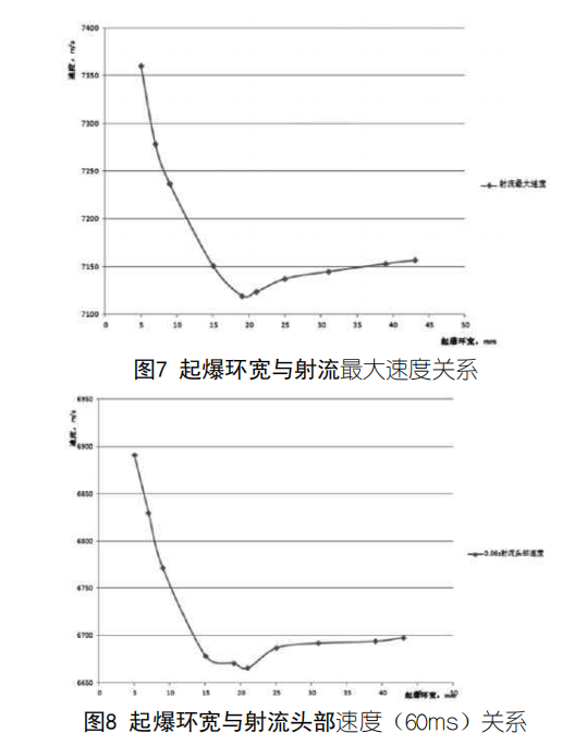
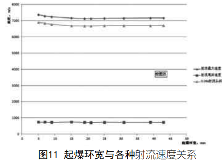
(1) From the above calculation, it can be seen that in the annular detonation system, as the width of the detonation ring increases, the maximum velocity of the jet and the velocity of the jet head first decrease and then rise.
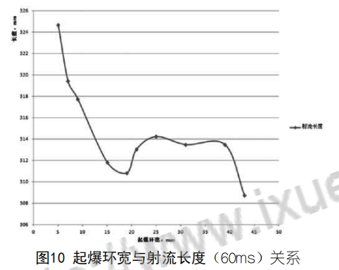
(2) The jet length first gradually becomes shorter and then rises as the width of the detonation ring increases.
(3) Through analysis, it can be seen that in the annular detonation system, the formation of the shaped charge jet can be greatly affected by adjusting the width of the detonation ring under certain conditions. Among the 10 schemes, the difference in jet speed is 3.37%, and the jet length is 5.16% different.
(4) When the annular detonation system detonates the shaped charge to form a jet, it controls the propagation shape of the detonation wave in the explosive by changing the width of the detonation ring, thereby changing the incident angle of the detonation wave to the charge cover and acting on the charge. The pressure on the cover controls the crushing speed and crushing angle of the medicine cover and affects the jet velocity.

4.2 Conclusion A shaped charge with good performance should not only have a sufficiently large jet velocity, but also have a reasonable jet velocity gradient distribution and mass distribution. The jet parameters are closely related to the detonation waveform of the charge. Therefore, in the design of the shaped charge waveform, a reasonable detonation ring width index for the annular detonation system should be proposed based on the specific requirements of the jet parameters.