This paper describes the interference phenomenon caused by using relays to control power loads in electronic circuits, analyzes the mechanism of interference and proposes solutions. The study found that the interference comes from spatial coupling, and the interference source is the spark generated by the relay contacts during making and breaking. The use of optical coupling isolation can make the relay work stably and prevent malfunctions from occurring. The correctness of the research results has been proven in practical applications.
1 Introduction
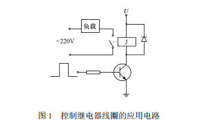
In actual automatic control systems, computers often need to control some high-power loads. In many cases, relays are widely used because they require small control power, low voltage, and are easy to interface with computers. For example: a relay controls the closing of a contactor, thereby controlling the operation of equipment such as AC motors. The actual application circuit of the relay is shown in Figure 1.

The load in Figure 1 is the coil of the intermediate relay that controls the inductive load. When the microcontroller controls the transistor to conduct, the relay coil is energized and the normally open contact is closed, so that the intermediate relay coil is energized and the AC motor works.
In order to solve the stability problem of the control system, this paper studies the changes in the power supply voltage of the electronic circuit during the operation of the relay and finds out the cause of the problem in view of the malfunctions that often occur in the circuit operation shown in Figure 1.
2 Research on interference phenomena in relay applications
From the circuit analysis, the interference comes from spatial coupling, and the source of interference should be the spark generated by the relay contact when connecting and breaking the intermediate relay coil. Because the coil of the intermediate relay is an inductive load, when the circuit is disconnected, the energy stored in the inductor will make it difficult to disconnect the circuit. The violent changes in the spark generated will radiate electromagnetic waves into the space, which may change the I/O port level of the microcontroller, causing Abnormal changes in the level output of the microcontroller. For this reason, a resistance-capacitance absorption circuit is connected in parallel to the normally open contact of the relay on the circuit board to reduce the spark energy between the contacts and reduce the probability of malfunction. But since the microcontroller still malfunctions, there must be another reason after analysis. It is likely that the power supply level of the microcontroller has changed. Therefore, the power supply voltage waveform at the two moments when the normally open contact of the relay is opened and closed is studied.
Figure 2 (a), (b), and (c) respectively show the power supply voltage waveforms at the moment when the normally open contact of the relay is turned on. It can be seen that there are sometimes jumping spikes on the power supply voltage. However, the amplitude, polarity, number and presence of spikes are random, which is consistent with the irregularity of system malfunctions.

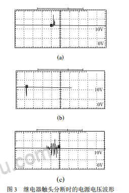
Figure 3 (a), (b), and (c) respectively show the power supply voltage waveform at the moment when the normally open contact of the relay is broken. It can be seen that there are also beating spikes on the power supply voltage. The amplitude, polarity, and number of the spikes are random and will appear every time. Judging from the actual system failure process, there are fewer malfunctions during connection and much more malfunctions during disconnection. Even after the malfunction, the control system no longer starts. The inspection found that the surface of the microcontroller 8255 close to the internal chip was burnt. Combined with the observed increase in the power supply voltage, it should be that high voltage burned out the chip. After analyzing the structure of the relay, it is believed that the reason for the high voltage is that the normally open contacts and the control coil of the relay are sealed in a small space. When sparks appear on the contacts, the changing electromagnetic field induces a high voltage in the control coil of the relay. , this high voltage acts on the power supply voltage system of the microcontroller, causing the power supply voltage of the microcontroller to spike. The upper and lower limits of the voltage fluctuation exceed the allowable power supply range of the microcontroller. Inside the microcontroller are various gate circuits integrated with microelectronics. Voltage fluctuations will This causes the gate circuit to work abnormally, resulting in unexpected output results.

The reason why the relay spark is small when it is turned on is because the contacts start to generate sparks when they are close, but the contacts close quickly and the sparks disappear; when the relay contacts are broken, sparks are generated just after they are separated, and the distance between the contacts increases. , the spark also increases until the energy provided by the power supply cannot maintain the existence of the spark, and the spark goes out.Therefore, the sparks when the relay is broken are much larger, causing more spikes in the power supply voltage when the relay is broken, and the microcontroller will malfunction more than when it is turned on.
3 Relay anti-interference measures
In order to prevent malfunction due to interference when the relay is working, the power supply voltage of the microcontroller must be isolated from the power supply voltage of the relay coil. Photoelectric isolation measures are used to isolate the relay supply voltage from the microcontroller supply voltage. In the actual circuit, a TL P521 optocoupler is used. The fluctuation of the secondary power supply voltage only acts on the output pole of the optocoupler. The withstand voltage of the optocoupler is 55 V, which can To meet the variation range of voltage spikes, the circuit is shown in Figure 4.
After the isolation of the optocoupler, the relay works stably and no more malfunctions occur. Even if the normally open contact does not add a resistance-capacitance absorption loop, malfunctions no longer occur. This indicates that malfunctions are caused by power supply voltage fluctuations, and electromagnetic waves in space Radiation as long as it is not in the relay control line of low-voltage appliances (2002 №4).

If the excessively high induced voltage generated in the circuit is superimposed on the power supply of the microcontroller, it will not affect the normal operation of the microcontroller. The above conclusion is drawn under the condition of AC motor of 1 kW.
4. Suggestions for high-power AC motor control. Although optocoupler isolation solves the problem of the working stability of the microcontroller, sparks from the relay’s normally open contacts will affect its contact life. Moreover, when the breaking and making currents are large, the radiated energy If it is increased, new unpredictable anomalies may appear. Therefore, it is recommended to use a triac optocoupler for strong and weak electrical isolation, as shown in Figure 5.
In Figure 5, when there is current input on the primary side of the optocoupler, the triac on the secondary side of the optocoupler is turned on, and when the load power supply voltage reaches a certain value, the high-power optocoupler gate is injected through the secondary side of the optocoupler. trigger

The high-power triac conducts current, and the load passes the current. Since there is no mechanical switch, there is no spark, and it will not interfere with the work of the microcontroller control system. In this way, the interference problem of sparks generated by the contacts and the electrical life problem of contact wear are simultaneously solved. It should be noted that when the voltage of the load power supply is low and the load current is small, the current of the triac must reach the holding current before it can be used normally.
5 Conclusion
Malfunction when the relay controls the AC motor is caused by the electromagnetic wave from the spark of the relay contact coupling from space to the relay control coil, causing induced potential, causing fluctuations in the power supply voltage of the microcontroller, causing voltage spikes. Isolating this voltage spike from the power supply of the microcontroller can eliminate malfunction of the relay.Keywords: 16-channel IO control


