Among the EIA standard series, the RS485 protocol is considered the most versatile, showing good performance in all four standards of serial communication. This is the reason RS485 is widely used as a communication interface when multiple nodes need to communicate in control or data acquisition applications.
RS485 signal line definition

| DB9 | Interface instructions | Pin name |
| 1 | CD CD | Carrier detection |
| 2 | RXD RXD | 接收数据Receive data |
| 3 | TXD TxD | 传输数据transfer data |
| 4 | DTR DTR | 数据终端就绪Data terminal ready |
| 5 | GND GND | 系统接地System ground |
| 6 | DSR DSR | 数据准备就绪data ready |
| 7 | RTS | 发送请求send request |
| 8 | CTS | 清楚发送send clearly |
| 9 | RI RI | 振铃指示器Ring indicator |
Carrier Detect (CD) This control signal is used when the serial server notifies the computer that it has detected a carrier that the computer can use for data transmission.
The receive data (RXD) line is used for data transfer between two sources. An example is the transmission of data received from a serial port server to a computer.
Transmission Data (TXD) This is the line that actually carries the transmission data.
Data Terminal Ready (DTR), a signal that the computer is ready to transmit.
System ground (GND) refers to the physical connection to the ground that is used as a baseline for measuring voltages in a circuit or as a shared path for return current.
Compared with the DTR signal, data ready (DSR), this signal informs the computer or terminal that the serial port server is running and able to receive data.
For this signal, a request to send (RTS) positive voltage is required to allow the request to send (RTS) to be performed. This indicates that interference-free transmission between the data set and the data terminal is possible.
After a connection is established between the data terminal and the serial port server, Clear to Send (CTS) sends this signal to confirm that the data terminal has confirmed that communication can begin.
The purpose of the Ringing Indicator (RI) is to alert the serial port server running the data set that a low frequency has been detected. This signal only alerts the data terminal and does not affect data transmission between devices.
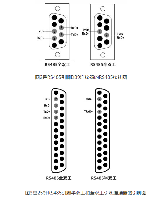
Pin assignment via 2 and 4 contacts to DB9 and DB25 connectors

The TxD and TxD-lines of the DB25 pin carry transmit data, while the RxD and RxD-lines contain receive data. These signals travel greater distances due to differential signaling.
The RS485 interface achieves longer distance and better data rate performance, which is superior to the RS232 protocol transmission method. Supports transmission speeds of 30-35 Mbps over a distance of up to 10 meters. Data rates of 100Kbps are achieved over distances of up to 1200 meters. RS485 is primarily used in multipoint configurations utilizing its balanced differential interface.
As shown in the RS485 cable pinout, this interface has all signals configured differentially.
● CTS and CTS- as well as RTS and RTS- signals are used as handshake control signals.
● TxD and TxD – perform data transfer.
● RxD and RxD – are the rows used to collect data.
Multi-drop configurations connect up to 32 devices to one control master. VSAT NMS (Network Management System) is an example. In this implementation, software running on the PC can monitor and control various subsystems. These include MUXes, modems, RF up/down converters, and other network components. In order for this type of implementation to work properly, a properly wired RS485 connector is required on the PC running the NMS application, as well as on all connected subsystems.
RS485 interface description
The RS485 (EIA485) interface has proven to be extremely robust and has become the most popular communication protocol in industry due to its multi-point topology. The RS422 protocol is similar to RS485 in that both use differential signals for data transmission.
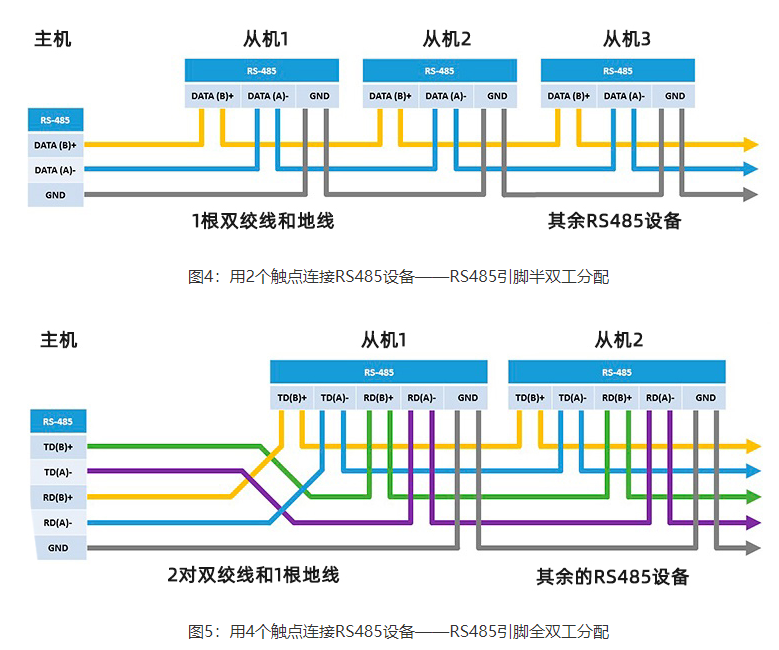
There are two types of RS485:
● Half-duplex RS485 has 2 contacts
● Use RS485 4 contacts in full duplex mode.
Full-duplex mode is used when you need to be able to send and receive data at the same time. In half-duplex mode, you can only send or receive data at any given time.
The voltage on the line ranges from -7 V to 12V.
There is no specific connector type for implementing the RS485 protocol, but in most cases, a DB9 connector or terminal block is used.
Specific RS485 connectors may have different pinouts. You will be able to determine the actual configuration from the documentation that comes with the device.

Keywords: Rail-type 4G DTU